
KEWO is a Chinese top manufacturer of AC drives, variable speed drive, Solar Pump drive,Soft Stater, Speed Controller...
Tel:86-0755-84186866,
MP:86-18038034988
Mail:service@kewoinverter.com Skye:gary.yu88
Tel:86-0755-84186866,
MP:86-18038034988
Mail:service@kewoinverter.com Skye:gary.yu88

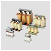
AC Output Reactor
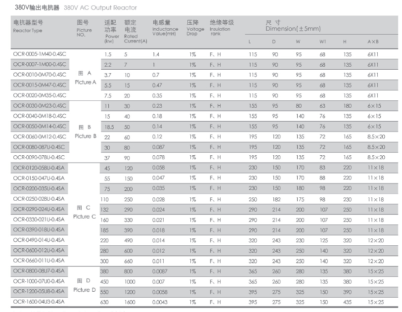
AC Out Put Reactor (OCR)
Production introduction:Line reactors used on the output side of a drive (load reactors)
Output reactors are recommended for operating "non-inverter-duty" motors and for any motors when the length of wiring between the AC drive and motor exceeds 75 feet. Protect the motor insulation against AC drive short circuits and IGBT reflective wave damage, and also allow the motor to run cooler by "smoothing" the motor current waveform.
Load reactors are also used on the output of AC Drives to reduce the effects of high motor wiring capacitance and to “soften” the dv/dt (high rates of change of voltage) applied to the motor windings.
This reactor is used for suppress the capacitive charging current of connection cable between inverter and motor, and passivating the voltage rising rated of PWM as well. It is mounted at the output side of frequency inverter. When the distance of cable between inverter and motor over a value, suggest installed output rector to compensate recharge current of line capacitive.
Product application
• Help meet IEEE 519 criteria by reducing harmonic distortion of the input line current.
• Improve input line current balance.
• Reduce nuisance drive over-voltage trips caused by transient voltage spikes and power line notches.
• Protect input rectifiers from in-rush current caused by sudden power line surges and sags.
• Extend the life of the DC bus capacitor bank by reducing the internal heating caused by ripple current.
• Protect motor windings from long lead effects when used on the drive output.
The use of line and load reactors increases the reliability, performance, and efficiency of VFD systems, extends the life of both drives and motors, and reduces the amount of energy consumed by the motor/drive system.
Working condition:
1. Working voltage: 220V/1140V
2. Working frequency: 50/60Hz
3. Rated current: 3A to 1600A
4. Carrier frequency: 2 to 8KHz,
5. Insulation class: Class F. H
6. Operation environment: No need derated suing during -10℃to 45℃, if work in above 45℃, the rated current will be reduce 2% for every 1℃rising.
7. Protection class: IP00-IP22.
8. Voltage drop: < 4%, if large than this value, the output torque of inverter will be lower.
9. overload tolerance capability: 1.5% rated current for 60s.
10. Noise: ≤65DB.
11. Temperature rise:≤85K
12: Dielectric strength: Steel wire core 3000VAC/50Hz/5mA/10s no electric arcing puncture.
13: Insulation resistor: 1000VDC insulation resistance value ≥100MΩ.
14: working under sea level below 2000m
15. Running condition: temperature-25℃to 45℃, comparative moisture not over 90%.
16: No hazardous gas, no inflammable and explosive
17: Good ventilation.


Prev:AC Input Reactor Next:DC Reactor
We are focusing on motor control over than 20 years---famous manufacturer of AC motor drive


 Item:1

